- What Slurry Pump Sizing Actually Means
- Key Parameters Required for Slurry Pump Sizing
- Step-by-Step Slurry Pump Sizing Process
- Understanding Slurry Pump Curves for Proper Sizing
- How Slurry Properties Affect Pump Size Selection
- Pipeline Design Considerations That Influence Pump Sizing
- Common Mistakes in Slurry Pump Sizing
- Practical Selection Framework: Choosing the Correct Slurry Pump Size
- Conclusion: Slurry Pump Sizing Is a System-Level Calculation
- FAQs: Slurry Pump Sizing and Calculation
What Slurry Pump Sizing Actually Means
Slurry pump sizing is the process of matching pump performance to the actual demands of a slurry transport system. It is not simply choosing a pump based on discharge size, horsepower, or catalog capacity. The goal is to make sure the pump can move the required volume of slurry through the full pipeline while overcoming all system resistance and maintaining stable solids transport.
Three variables define slurry pump sizing: flow rate, total dynamic head, and slurry properties. Flow rate determines how much material must be moved. Total dynamic head defines how much resistance the pump must overcome. Slurry properties determine how the material behaves in the line and how strongly it affects friction, wear, settling reisk, and power demand.
Accurate sizing directly impacts system performance, wear life, and operating cost. A correctly sized pump maintains stable flow, keeps solids from settling in the pipeline, and operates in a controllable range. An incorrectly sized pump can lead to settling, blockage, inefficient power use, excessive wear, and unstable system behavior.

Key Parameters Required for Slurry Pump Sizing
Flow Rate (Q)
Flow rate is the volume of slurry the system must move over time, usually expressed in gallons per minute (GPM) or cubic meters per hour (M3/hr). It is typically defined by production targets such as dredging output, solids transfer rate, or process throughput.
Flow rate cannot be evaluated on volume alone. It also has to maintain enough pipeline velocity to keep solids suspended. If velocity drops below a critical transport velocity, particles begin to settle, resistance increases quickly, and blockage risk rises. In slurry systems, stable flow depends on staying above settling velocity.
Total Dynamic Head (TDH)
Total dynamic head represents the total resistance the pump must overcome to move slurry through the system. It includes:
- static head from elevation differences
- friction losses from pipe walls
- minor losses from bends, valves, reducers, and fittings
Friction losses increase with pipeline length, velocity, slurry density, and line roughness. Even modest changes in pip diameter, routing, or fitting count can change the total head meaningfully. TDH is one of the primary inputs that defines the required pump operating point.
Slurry Properties
Slurry behavior has a direct impact on pump sizing. Key inputs include:
- solids concentration by weight or volume
- particle size and distribution
- specific gravity of the slurry
- viscosity and flow characteristics
Higher solids concentration increases resistance, load, and power demand. Larger particles require enough internal clearance and can raise wear rate significantly. Because slurry rarely stays perfectionly consistent in the field, sizing should account for realistic operating ranges rather than one fixed condition.
Pipeline Characteristics
The pipeline defines how resistance builds through the system. Important factors include:
- pipe diameter and internal roughness
- total pipeline length
- number and type of fittings
- horizontal and vertical layout
A smaller diameter pipe increases velocity but also increases friction loss. A larger diameter pipe reduces friction but may let solids to settle if velocity becomes too low. The pump and pipeline must be sized together, not separately, if the system is going to perform reliably.
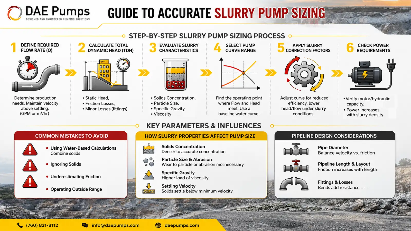
Step-by-Step Slurry Pump Sizing Process
Step 1: Define Required Flow Rate
Start by defining the required slurry flow rate based on production, transfer, or dredging targets. Then confirm that this flow rate also maintains enough velocity to keep solids suspended throughout the pipeline.
Step 2: Calculate Total Dynamic Head
Break total dynamic head into its parts:
- static head from elevation differences
- friction losses from pipe length, diameter, and velocity
- minor losses from fittings, bends, valves, and reducers
Use friction estimates appropriate for slurry systems instead of relying only on clean-water assumptions. Water-based calculations can be a starting point, but they are not enough for final pump selection.
Step 3: Evaluate Slurry Characteristics
Determine slurry density, solids concentration, particle size, specific gravity, and settling behavior. These values affect friction loss, power demand, wear, and actually pump performance. Dense slurry and larger particles require more energy to move and create more demanding operating conditions.
Step 4: Select Pump Curve Range
Identify a pump curve that intersects the required flow rate and total dynamic head. That intersection defines the expected operating point. Because pump curves are usually based on water, they should be treated as a baseline rather than the final answer in slurry service.
Step 5: Apply Slurry Correction Factors
Adjust the water-based pump curve for slurry conditions. In real slurry service, pump efficiency drops, power demand rises, and achievable head or flow may shift. These corrections bring the selection closer to real operating conditions.
Step 6: Check Power Requirements
Verify that the required power stays within available motor or hydraulic limits. Power demand rises with slurry density, solids concentration, and total system resistance. The selected pump must operate within the available power envelope under real conditions, not just under ideal assumptions.

Understanding Slurry Pump Curves for Proper Sizing
Pump curves show the relationship between flow and head. The actual operating point is where the system curve intersects the pump curve. That intersection defines how the pump will perform once it is installed.
Pump curves are usually generated using water, not slurry. Once solids are introduced, the operating point shifts because slurry changes friction, density, efficiency, and power demand. That means that the real operating point will not match the water curve exactly.
Key considerations include:
- operating near the best efficiency point improves stability and wear life
- avoiding the far ends of the curve reduces instability, heat, and wear
- matching the system curve to the pump curve improves predictability
Pump sizing is not complete until the pump curve and the real system curve are evaluated together.
How Slurry Properties Affect Pump Size Selection
Solids Concentration Impact
As solids concentration increases, the slurry becomes heavier and more difficult to move. This increases energy demand, raises friction loss, and usually requires more power to maintain stable flow.
Particle Size and Abrasion
Larger particles require enough internal clearance to prevent blockage and often increase wear rate. Pump selection has to account for both particle size and abrasiveness if long-term reliability matters.
Slurry Density and Specific Gravity
Specific gravity directly influences head correction, hydraulic load, and power demand. . Higher specific gravity increases the effective load on the pump, so it has to be included in sizing calculations.
Settling Velocity
Every slurry has a minimum transport velocity needed to keep particles suspended. If flow velocity drops below that threshold, solids begin to settle, resistance rises sharply, and flow becomes unstable. Proper sizing must keep line velocity above settling velocity.

Pipeline Design Considerations That Influence Pump Sizing
Pipe Diameter Selection
Pipe diameter affects both transport velocity and friction loss. A smaller diameter pipe increases velocity but also increases resistance. A larger diameter pipe reduces resistance but may allow solids to settle if velocity drops too low. The correct diameter balances these pressures.
Pipeline Length and Layout
Longer pipelines increase friction loss. Vertical lift adds static head. Complex routing adds additional resistance. Pipeline layout must be included in the TDH calculation or the pump will likely be undersized.
Fittings and System Losses
Each bend, valve, reducer, and transition fitting adds resistance. These losses accumulate and can materially increase TDH. Ignoring them is one of the easiest ways to under-size a slurry pump.
System Curve Interaction
The system curve shows how resistance changes with flow changes. The pump has to operate where the system curve intersects the pump curve. Any changes in diameter, elevation, routing, or fitting shifts the system curve and therefore changes the operating point.
Common Mistakes in Slurry Pump Sizing
- using water-based calculations without correcting for slurry behavior
- ignoring solids concentration, density, or particle size
- selecting pipe diameters without checking transport velocity
- Underestimating friction losses from fittings and layout
- Operating the pump outside its optimal range
- Not verifying power availability
- Assuming slurry properties remain constant
Practical Selection Framework: Choosing the Correct Slurry Pump Size
- If the slurry contains high solids or variable material, prioritize pump designs that can handle changing conditions and solids movement more reliably
- If the pipeline is long, focus on friction reduction, velocity control, and accurate TDH calculation
- If the material settles quickly, maintain sufficient line velocity to prevent accumulation
- If power is limited, optimize the pipeline before simply choosing pump size
- If abrasion is severe, evaluate wear materials and pump alongside pump size
The correct slurry pump size is the one that maintains stable transport, meets required flow and head, stays within available power, and fits the actual slurry behavior in the system.
Conclusion: Slurry Pump Sizing Is a System-Level Calculation
Slurry pump sizing depends on accurately defining flow rate, total dynamic head, and slurry behavior. These variables are interconnected, and a change in one usually changes the others.
The pump, pipeline, and slurry must be evaluated together. Selecting a pump based on isolated specifications usually leads to unstable operation, avoidable wear, or poor transport performance. Accurate sizing comes from understanding how the full system behaves and then matching the pump to that reality.
The practical takeaway is simple: slurry pump sizing is not a catalog exercise. It is a system decision. When flow, head, slurry behavior, and pipeline design are aligned, the result is more stable performance, lower wear, and fewer surprises in the field.
FAQs: Slurry Pump Sizing and Calculation
How do I choose the correct slurry pump size?
Determine the required flow rate, calculate total dynamic head, and account for slurry properties such as density, solids concentration, and particle size. The correct size is the pump that meets those conditions at a stable operating point.
What is the most important factor in slurry pump sizing?
There is no single most important factor. Flow rate, total dynamic head, slurry properties, and pipeline design all have to be evaluated together.
Can I use water pump calculations for slurry systems?
Water-based calculations can be a starting point, but they must be adjusted for slurry density, solids behavior, and higher friction losses before final selection.
How does slurry density affect pump size?
Higher slurry density increases resistance, load, and power demand. That usually requires a pump that can deliver more energy while still maintaining transport velocity.
What happens if a slurry pump is undersized?
An undersized slurry pump may fail to maintain required velocity, which can cause settling, rising resistance, lower output, and unstable operation.
What happens if a slurry pump is oversized?
An oversized slurry pump may operate inefficiently, drift away from its preferred range, increase wear, and reduce overall system stability.